Industries · Aerospace and defence
Build-to-print PCB manufacturer for aerospace and defence
Bare boards and assemblies made to a prime contractor's drawing: IPC Class 3 on request, multilayer to 12 layers, components from authorised distributors only, and a build record that traces every board back to its lot. Your programme's qualification stays with you.
| IPC-6012 | Class 2 | Class 3 |
|---|---|---|
| B Hole-wall copper, average | 20 µm | 25 µm |
| A External annular ring | 90° breakout allowed | 0.050 mm min. |
Our design guideline for drilled holes is a 0.15 mm annular ring. Limits per IPC-6012; your drawing names the revision.
- Build class on request
- IPC Class 3
- Layers
- 1–12
- Components
- Authorised only
- Electrical test
- 100%
01Overview
What does aerospace and defence work ask of a PCB supplier?
In aerospace and defence the board is rarely the product. It is one line on a sub-assembly's parts list — a power-conditioning card, an interface board, a display driver — built to a drawing owned by the prime contractor or design authority and released under their qualification.
What that buyer needs from a board shop is exactness and evidence: the drawing's revision, materials and acceptance class met on every lot, and the records to show it. We build to IPC Class 3 on request — thicker hole-wall copper, a larger minimum annular ring and stricter inspection limits than the Class 2 default.
We are ISO 9001:2015 certified. We do not hold AS9100 or a defence-sector approval, and we do not claim one: those belong to the organisation that releases the equipment. Our part is a board that meets the print, and a record that proves it.
Last updated
02Board selection
Which boards does aerospace and defence equipment use?
| Board in the product | Construction | Base material | Finish | IPC class |
|---|---|---|---|---|
| 01Power-conditioning and DC-DC converter cards | 4–6 layer multilayer | FR-4 Tg 170 °C, 2 oz copper | ENIG | Class 3 |
| 02Processor, interface and I/O cards | 6–12 layer multilayer | FR-4 Tg 170 °C, controlled impedance | ENIG | Class 3 |
| 03Sensor, telemetry and data-acquisition boards | 4–8 layer multilayer | FR-4, controlled impedance | ENIG | Class 3 |
| 04Display, keypad and control-panel boards | 4–6 layer multilayer | FR-4 | ENIG | Class 3 |
| 05Ground-support, test and interface-adaptor boards | Double-sided PTH | FR-4 | Leaded or lead-free HASL | Class 2 · 3 |
| 06Board-to-board flexible interconnects | Single- or double-sided flex | Polyimide with coverlay | ENIG | Class 2 · 3 |
Drawings for this work usually fix the laminate, finish, class and marking. Where yours is silent, we raise a query before tooling rather than choose for you.
03Engineering
High-reliability board problems, and how we solve them
Equipment that cannot be allowed to fail fails in a few well-known ways. These are the ones the board and its assembly can prevent.
- Vibration
- Thermal cycling
- Traceability
- Lifetime
- Humidity
P1Vibration
Shock and vibration find the weakest joint
Annular ring ≥ 0.15 mm guidelineWhy boards fail
Vehicle-, airframe- and launcher-mounted electronics see sustained vibration and repeated shock. Heavy parts load their solder joints, the board flexes, and a thin plated barrel or a marginal annular ring is where the crack starts.
How we handle it
Class 3 calls for more copper in each hole wall and an annular ring with no breakout; designing to our 0.15 mm annular-ring guideline leaves margin for drill wander. Assemblies are built to IPC-A-610 Class 3, with BGA joints X-rayed.
P2Thermal cycling
Temperature swings fatigue plated holes
FR-4 Tg 170 °CWhy boards fail
Altitude, desert ground-soak and cold starts take a board through a wide temperature range again and again. The laminate expands through its thickness far more than copper does, and every cycle strains the barrel of every plated hole.
How we handle it
High-Tg FR-4 (Tg 170 °C) stays in its low-expansion range over a wider band of operating temperatures, and Class 3 plating gives each barrel more copper to carry the strain. Thick, many-layer boards are where both matter most.
P3Traceability
Counterfeit parts end programmes
Lot + date code per partWhy boards fail
A remarked or recycled component can pass an incoming visual check and fail in the field years later. Long programmes buy parts long after they are current, which is exactly when broker stock looks tempting.
How we handle it
Authorised distributors and manufacturers only — no grey-market or broker stock. Lot and date-code traceability on every part, recorded against the job, so any board can be traced back to the reels and trays it was built from.
P4Lifetime
Programmes outlive their parts lists
Revision-controlled repeatsWhy boards fail
An equipment type can stay in service for decades. Repeat orders arrive years apart against a drawing revision that must be matched exactly, while some of the original parts have gone end-of-life.
How we handle it
Each job is built to the drawing revision named on the order, and your specification stays on file for the repeat. BOMs are reviewed for lifecycle (EOL / NRND); an alternate part is proposed, never fitted, without your written approval.
P5Humidity
Condensation and residue under the coating
Coating and cleanliness on the drawingWhy boards fail
Equipment that cycles between cold altitude and humid ground collects condensation. Under a conformal coat, ionic residue left on the board draws moisture in and grows leakage paths between closely spaced conductors.
How we handle it
Put the coating — acrylic, silicone, urethane or parylene — its keep-outs and any cleanliness limit on the assembly drawing. We choose a mask and finish the coating adheres to, and agree at quotation how the build will meet the cleanliness limit.
04Applications
Aerospace and defence equipment we build boards for
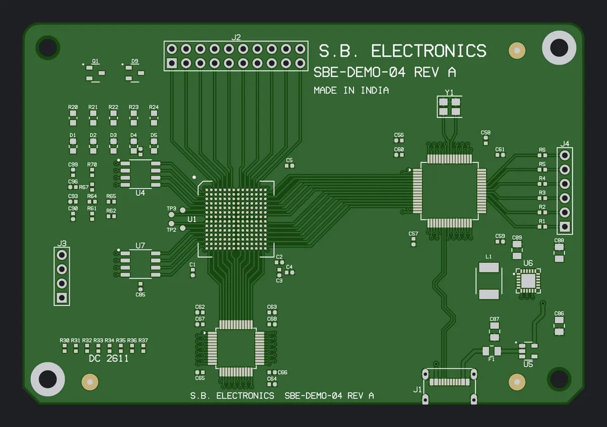
- A14–8 L
UAV flight and payload electronics
Flight controllers, power distribution and payload interface boards
- A26–12 L
Communication sub-assemblies
Interface, control and power boards for radio and data-link equipment
- A34–6 L · 2 oz
Power supplies and converters
DC-DC, power-conditioning and distribution cards
- A44–6 L
Displays and control panels
Operator displays, keypads and panel controller boards
- A52–6 L
Ground-support and test equipment
Test sets, interface adaptors and harness testers
- A62–8 L
Simulators and trainers
I/O, interface and display boards for training systems
- A74–8 L
Data acquisition and telemetry
Sensor conditioning, data loggers and telemetry boards
- Not listed?Send the drawing and a line about where the board will be used.Ask an engineer
05Specification
A starting specification for Class 3 build-to-print
| Acceptance class | IPC-6012 Class 3 bare board; IPC-A-610 Class 3 assemblyOn request; Class 2 is our standard |
|---|---|
| Construction | 4–12 layer multilayer; double-sided PTH for test and interface boardsRange: 1 to 12 layers |
| Laminate | FR-4 Tg 170 °CAvailable: FR-4 (Tg 150 °C / Tg 170 °C), FR-2, CEM-1, CEM-3, polyimide (flex) |
| Board thickness | 0.4 mm to 3.2 mm standard; 0.2 mm for thin rigid designs1.6 mm default; thicker for many-layer boards carrying heavy parts |
| Copper weight | 1 oz (35 µm) and 2 oz (70 µm) standard; 3 oz (105 µm) and heavier on request |
| Min. track / space | 6 mil / 6 mil standard; 4 mil / 4 mil fine-lineStay at 6 mil / 6 mil where the layout allows: Class 3 inspection is less forgiving of fine-line etch variation |
| Annular ring | 0.15 mm minimum for drilled holes (design guideline)Comfortably above the Class 3 external minimum in IPC-6012 |
| Impedance control | Controlled impedance, ±10% tolerance, with stack-up design support |
| Surface finish | ENIG; leaded HASL where the drawing permits tin-leadAvailable: HASL · LF-HASL · ENIG · OSP |
| Marking | Part number, revision and date code in the legend, as the drawing specifies |
| Electrical test | 100% electrical test — flying probe or bed-of-nails fixture — plus AOI |
| Assembly inspection | AOI at every stage; X-ray for BGA; functional test on requestIPC-A-610 Class 2 standard; Class 3 on request |
| Components | Authorised distributors and manufacturers only — no grey-market or broker stockLot and date-code traceability on every part |
How to order this spec
Priced online
Simple fixture and interface-adaptor boards (rigid single- and double-sided boards) can be priced online — 10 mm to 600 mm per side, dispatch in 3, 5, 7 or 10 working days. Class 3 work is not priced online.
Open the instant quoteReviewed by an engineer
Class 3 builds, multilayer, assembly and any job with marking or documentation requirements are reviewed against the drawing by an engineer, who aims to reply within 24 hours on working days.
Request a quote06Build to print
Building to the drawing, note by note
Fabrication notes · unless otherwise specified
Specimen
Fabricate and accept per IPC-6012, Class 3.
Built and inspected to Class 3: more copper in every hole wall, no annular-ring breakout. Class 2 is our default, so the class is confirmed at CAM review.
Production stages: CAMPLTFQC
Material: FR-4, Tg 170 °C min.
We build on FR-4 at Tg 150 °C and Tg 170 °C. Where a note names an IPC-4101 slash sheet, the laminate datasheet is matched to it at quotation.
Production stages: CAM
Controlled impedance: 50 Ω ±10% on nets marked Z1.
The stack-up is modelled and line widths are tuned in CAM to hold ±10%. Any width change comes back to you for approval first.
Production stages: CAMETC
All hole sizes are finished sizes, after plating.
Each drill is sized up in CAM to allow for the plating, so the finished hole meets the drawing. Smallest drill: 0.3 mm mechanical; 0.2 mm for fine-pitch designs.
Production stages: CAMCNCPLT
Finish: ENIG. Tin-lead HASL acceptable.
ENIG and leaded HASL are both standard finishes on our line. Lead-free is our default, so a tin-lead allowance is confirmed with you, never assumed.
Production stages: FIN
Mark P/N, revision and date code (YYWW) in legend, non-conductive ink, where shown.
Printed with the legend in white, yellow or black ink, where the drawing places it. The date code ties each board to its lot and its job card.
Production stages: LEG
100 % electrical test of all nets.
Every net is checked for opens and shorts by flying probe or bed-of-nails fixture, then the boards are inspected to IPC-A-600 before packing.
Production stages: E-TFQC
No deviation from this drawing without written approval of the design authority.
Every query goes back to you in writing before tooling. Nothing on the drawing changes, and no alternate part is fitted, without your written approval.
Production stages: CAM
- Title
- Interface card, bare board
- Drawing no.
- Your P/N
- Rev
- C
- Layers
- 6
- Class
- IPC-6012 Class 3
- Scale
- NTS
- Sheet
- 1 of 2
07Standards context
Which standards govern aerospace and defence boards?
- IPC-6012 Class 3
- Qualification and performance of rigid printed boards — high-reliability class
- Sets plating thickness, annular ring, microsection and cleanliness limits. Its space and military-avionics addendum adds further requirements when a drawing calls it up.
- IPC-A-610 / J-STD-001
- Acceptability of electronic assemblies; soldering requirements
- Class 3 workmanship criteria for solder joints, and the process requirements behind them.
- AS9100
- Quality management for aviation, space and defence organisations
- Held by the prime contractor or supplier that releases the product. It builds on ISO 9001; our quality system is ISO 9001:2015 certified.
- JSS 55555
- Environmental test methods for Indian defence equipment
- Vibration, shock, temperature and humidity tests run on the finished equipment, not on the bare board.
- IPC-CC-830
- Qualification and performance of conformal coatings
- Covers the coating material; the board's cleanliness and mask decide how well it adheres.
Stays with you
AS9100 certification, design-authority and programme approvals, environmental qualification (JSS 55555 or your own specification) and the release of the equipment stay with the prime contractor or supplier. We hold no sector approval and build to your released drawing.
Comes from us
Boards to IPC-6012 Class 3 and assemblies to IPC-A-610 Class 3 on request, to the drawing revision on your order; AOI, X-ray of BGAs and a 100% electrical test; parts from authorised distributors with lot and date-code traceability; an ISO 9001:2015 certified quality management system.
09FAQ
Aerospace and defence: common questions
Not covered here? Ask an engineer — we aim to reply within 24 hours on working days.
What PCB is used in aerospace and defence electronics?
Are you AS9100 certified or defence approved?
Who makes defence PCBs in India?
Can you build to print from our drawing and fabrication notes?
Can you supply tin-lead finishes and leaded soldering?
Aerospace and defence
Send the drawing. We build to it, and show that we did.
Upload Gerbers, drill data, the fabrication drawing and your class and marking requirements. An engineer reviews the package and replies with queries and a quote.