Industries · Industrial electronics
Industrial electronics PCB manufacturer in India
Boards for PLCs, drives, instruments, meters and control panels — equipment that runs for a decade in a hot, dusty, electrically noisy plant. Double-sided PTH and multilayer FR-4, made in Gandhinagar since 2000.
- Layers
- 1–12
- Impedance control
- ±10%
- Assembly
- SMT + through-hole
- Minimum order
- None
01Overview
What does industrial electronics ask of a PCB?
Industrial equipment is bought to run, not to be replaced. A PLC I/O card, a drive's control board or a process indicator is expected to work for a decade beside contactors, motors and welding sets — and to be repairable when it does not.
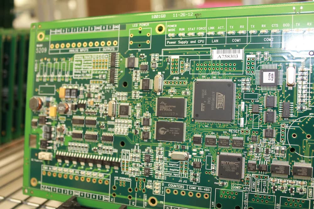
That keeps the board on proven constructions: double-sided plated-through-hole FR-4 for I/O, relay and power-supply cards, and four- to six-layer boards with solid ground planes for processor, communication and HMI boards. Terminal blocks, relays and transformers still mean through-hole, so mixed-technology assembly matters as much as fine pitch.
Instrumentation makers such as Masibus are on our customer list. The prototype of a new transmitter and the hundredth repeat of a meter that has been in the catalogue for years come off the same line.
Last updated
02Board selection
Which boards does industrial equipment use?
| Board in the product | Construction | Base material | Finish | IPC class |
|---|---|---|---|---|
| 01PLC digital and analogue I/O cards | Double-sided PTH | FR-4 | Lead-free HASL | Class 2 |
| 02Controller, CPU and communication boards | 4–6 layer multilayer | FR-4, controlled impedance | ENIG | Class 2 |
| 03Drive control and gate-drive boards (VFD, servo) | 4 layer multilayer | FR-4, Tg 170 °C | ENIG | Class 2 · 3 |
| 04Drive and SMPS power stages | Double-sided PTH | FR-4, heavy copper | Lead-free HASL | Class 2 |
| 05Panel meters, indicators and transmitters | Double-sided PTH or 4 layer | FR-4 | ENIG or lead-free HASL | Class 2 |
| 06HMI, keypad and display boards | 4–8 layer multilayer | FR-4 | ENIG | Class 2 |
Terminal blocks, relays and transformers still need through-hole: our line assembles SMT, through-hole and mixed-technology boards, so a mixed board needs no second supplier.
03Engineering
Industrial board problems, and how we solve them
A plant is hard on electronics in slow, cumulative ways: noise, heat, dust and years of service. These are the failures we design the build against.
- EMC
- Signal integrity
- Voltage
- Thermal
- Lifetime
P1EMC
Motors and drives fill the cabinet with noise
1–12 layers · stack-up supportWhy boards fail
Fast switching edges, contactor arcs and long field cables couple noise into analogue inputs and communication lines. A two-layer board with no continuous return path is usually where it gets in.
How we handle it
Move noise-sensitive designs to four layers with an unbroken ground plane under the signal layer. We build 4, 6, 8, 10 and 12 layers and help with the stack-up, so reference planes sit where your layout needs them.
P2Signal integrity
Fieldbus and Ethernet need a defined impedance
Impedance ±10%Why boards fail
RS-485, CAN, PROFIBUS and industrial Ethernet run on differential pairs that expect a set impedance. When dielectric height and track width drift, reflections show up as intermittent communication faults on site.
How we handle it
We build controlled-impedance boards to ±10% tolerance, with the stack-up agreed before fabrication. State the target impedance and the pairs it applies to on your drawing.
P3Voltage
Mains and field wiring share one board
Routed slots · 100% E-testWhy boards fail
One card can carry 230 V or 415 V mains, 24 V field I/O and 3.3 V logic. The safety standard sets creepage and clearance between them, and conductive plant dust shortens the effective distance.
How we handle it
Spacing and isolation slots are checked against your drawing before tooling; slots and outlines are CNC-routed (±0.15 mm as standard; ±0.1 mm on request); a 100% electrical test then proves no net touches another.
P4Thermal
Sealed enclosures keep the heat in
FR-4 Tg 170 °CWhy boards fail
IP-rated enclosures keep dust out and heat in. Power supplies, drive stages and relay drivers run warm for years, which ages laminate and stresses plated holes.
How we handle it
Specify high-Tg FR-4 (Tg 170 °C) for hot power boards and heavier copper for current-carrying tracks — 1 oz (35 µm) and 2 oz (70 µm) standard; 3 oz (105 µm) and heavier on request.
P5Lifetime
Ten years in service, and repairable
Same build on every repeatWhy boards fail
Industrial products stay in production for years and in the field for longer. A mid-life change of laminate or finish forces re-qualification, and boards must survive component replacement at service centres.
How we handle it
Repeat orders stay on the same laminate, finish and process. Lead-free HASL and ENIG both tolerate rework, and pads follow our annular-ring guideline (0.15 mm minimum for drilled holes) so they survive a part change.
04Applications
Industrial applications we build for
- A12–6 L
PLCs and remote I/O
CPU, digital and analogue I/O, and communication cards
- A22–4 L · heavy Cu
VFD and servo drives
Control, gate-drive and power boards
- A32–4 L
Process instrumentation
Transmitters, indicators, controllers and recorders
- A42 L
Energy and panel meters
Single- and three-phase meters, multifunction meters
- A51–2 L
DIN-rail power supplies
Isolated 24 V supplies and battery chargers
- A64–8 L
HMI and operator panels
Display, keypad and touch-controller boards
- A72–6 L
Test and measurement
Data loggers, calibrators and test fixtures
05Isolation
Creepage and clearance on a mixed-voltage card
The surface path now runs round the slot's end, so the same pad spacing gives a much longer creepage distance. Clearance, the straight line through air, does not change.
Drawing notes
- N1
Distances come from your standard
Working voltage, pollution degree and the laminate's material group (CTI) set the minimum creepage and clearance in the tables of IEC 60664-1 and the product standards that cite it.
- N2
A slot has to be wide enough to count
A groove only breaks the surface path above a minimum width — 1 mm at pollution degree 2 under IEC 60664-1. Draw the slot at its finished width on the mechanical layer.
- N3
We hold what you draw
Slots and outlines are CNC-routed (±0.15 mm as standard; ±0.1 mm on request); CAM checks copper-to-copper and copper-to-edge spacing against your drawing before tooling; the electrical test proves isolation between nets.
06Specification
A starting specification for industrial boards
| Construction | Double-sided PTH for I/O and power; 4–6 layers for controllersRange: 1 to 12 layers |
|---|---|
| Laminate | FR-4; Tg 170 °C for power and drive boards |
| Board thickness | 0.4–3.2 mm1.6 mm default; thicker for large boards carrying terminal blocks |
| Copper weight | 1 oz (35 µm) and 2 oz (70 µm) standard; 3 oz (105 µm) and heavier on request |
| Min. track / space | 6 mil / 6 mil standard; 4 mil / 4 mil fine-line |
| Min. drill | 0.3 mm mechanical; 0.2 mm for fine-pitch designs |
| Impedance control | Controlled impedance, ±10% tolerance, with stack-up design support |
| Surface finish | Lead-free HASL for through-hole-heavy boards; ENIG for fine pitchAvailable: HASL · LF-HASL · ENIG · OSP |
| Mask and legend | Green mask, white legend — best contrast for inspection and service |
| Electrical test | 100% electrical test — flying probe or bed-of-nails fixture — plus AOI |
| Assembly | SMT, through-hole (THT) and mixed technologyIPC-A-610 Class 2 standard; Class 3 on request |
| Components | Authorised distributors and manufacturers only — no grey-market or broker stock |
How to order this spec
Priced online
I/O, relay and power-supply boards — rigid single- and double-sided boards — are priced live: 10 mm to 600 mm per side, 1 to 100,000 boards per line, dispatch in 3, 5, 7 or 10 working days.
Open the instant quoteReviewed by an engineer
Multilayer controllers, impedance-controlled boards, assembly and component sourcing are quoted by an engineer, who aims to reply within 24 hours on working days.
Request a quote07Standards context
Which standards does industrial equipment follow?
- IEC 61010-1
- Safety of measurement, control and laboratory equipment
- Sets creepage and clearance for instruments and controllers by voltage, pollution degree and material group.
- IEC 61131-2
- Programmable controllers — equipment requirements and tests
- PLC hardware: the environmental, EMC and safety tests your I/O cards are part of.
- IEC 61800-5-1
- Adjustable-speed drive systems — safety
- Insulation coordination for a drive's power and control boards.
- IEC 61000-6-2 / -6-4
- EMC immunity and emission in industrial environments
- Your product's EMC test; ground planes and stack-up are where the board helps.
- IEC 60664-1
- Insulation coordination for low-voltage equipment
- The source of the creepage and clearance tables other standards refer to.
Stays with you
Product safety (IEC 61010, 61131-2, 61800-5-1), EMC compliance and any CE or BIS marking stay with the equipment maker. The board is one component of a tested product.
Comes from us
Boards built to IPC Class 2 by default, Class 3 on request, to your drawing and stack-up, with AOI, a 100% electrical test, final inspection to IPC-A-600 and an ISO 9001:2015 certified quality management system.
09FAQ
Industrial electronics: common questions
Not covered here? Ask an engineer — we aim to reply within 24 hours on working days.
What PCB is used in industrial electronics?
Do you make PCBs for PLCs and VFD drives?
Can you control impedance for RS-485, CAN or Ethernet?
Can you build small batches of an older industrial board?
Which surface finish is best for industrial boards?
Industrial electronics
Send the card. We will build it the same way every time.
Upload Gerbers, drill files and your stack-up or impedance targets. An engineer reviews them and replies with a quote; plain double-sided cards can be priced online straight away.